ROBOTICS / MECHANICS & CONTROL
Quadruped
MPC Control
I built a simulated quadruped, reduced walking-speed error by 72% from its initial controller, and kept motor control running independently of motion planning.
My role Mechanical modeling, leg kinematics, walking controllers, and simulation testing.
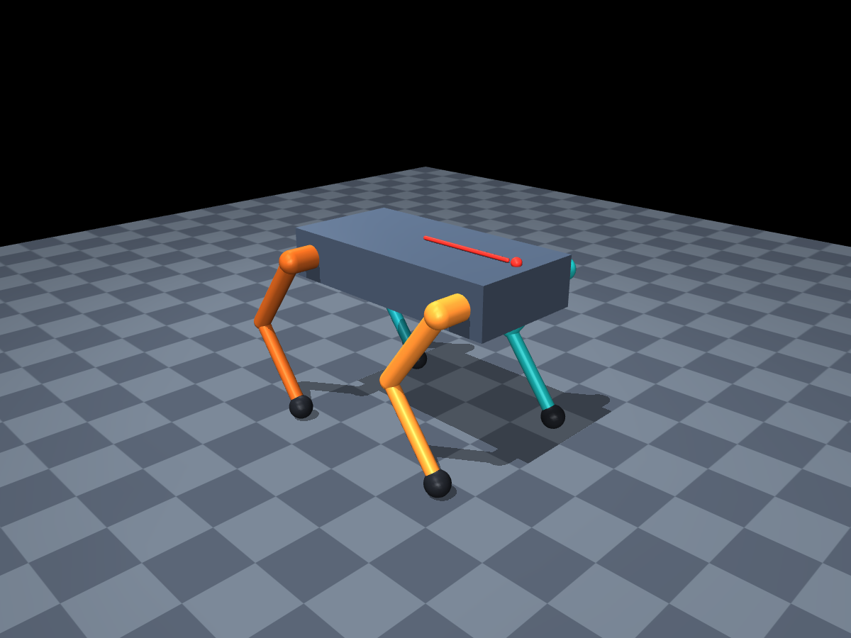
CUSTOM MECHANICAL MODEL · SIMULATION-ONLY VALIDATION
*Compared with the initial joint-position controller in 20 s simulations with ideal motors; includes gait and controller improvements.
01 / ENGINEERING PROBLEM
Making the robot walk
and follow a command
Getting the legs to move was only the first step: the robot also had to follow a requested speed without slipping or exceeding motor limits. I progressed from joint-position control to choosing foot forces, then to planning those forces ahead of time. The final challenge was letting that slower planning run without interrupting motor updates.
02 / METHODS & ANALYSIS
How I developed the system
Model → walking control → independent planning
Build and check the robot model
Improve how closely it follows the requested speed
The initial trot stayed upright but tracked speed poorly. I added ground-reaction-force (GRF) control to choose how each foot pushes against the ground, then model predictive control (MPC) to plan those forces ahead.
Walking-speed error m/s · root mean square error · lower is better
Requested speed: 0.15 m/s
This reduced the conflict between pushing forward and keeping the body balanced.
A force plan could be valid while the legs still drifted; a small restoring torque controlled that motion.
Keep motor updates running while planning
A new motion plan took longer than one motor-update interval. I moved planning into a separate process so motor control could use the latest valid plan without waiting.
MOTOR CONTROLLER Updates targeted every 2 ms
- Read the robot’s motionJoint positions, body motion, and foot contact
- Use the latest valid force planSwitch to GRF control if the plan is unusable
- Update joint torquesContinue moving the simulated robot
The two processes run independently.
MOTION PLANNER (MPC) New plans targeted every 10 ms
- Read the copied measurementsStart from the robot’s current motion
- Plan the foot forcesAccount for balance, grip, and motor limits
- Send back the new planMotor control checks it before use
Learn more: timing measurements and failure tests
How quickly did a new plan become usable?
Across five 20 s desktop trials, an average of 6.62 ms elapsed from reading robot motion to using a new foot-force plan; 99% of used plans took 8.65 ms or less. These figures include calculation and transfer time, and exclude rejected plans.
Did motor updates stay on schedule?
The target was one update every 2 ms. The average rate reached 500 updates per second, but 1.76% finished late, so this is not a guaranteed real-time controller.
What happened when planning failed?
I added computation load, paused planning for 120 ms, injected 20 invalid plans, and stopped planning 6 s into a 12 s test. The GRF controller took over and the robot passed the walking checks.
The simulated robot also pauses when its main program pauses; physical hardware would not. These tests demonstrate software behavior, not hardware safety.
03 / RESULTS & OUTCOME
Simulation results
Nominal walking 10 s · normal speed
Lateral push 12 s · half speed
In each clip, left to right: foot-force control, predictive control, and planning separate from motor control. Motor models differ.
Simulation only; physical robot testing is still needed.