UBC / RESEARCH PROJECT
Compact Design of a Precision XY Positioning Stage
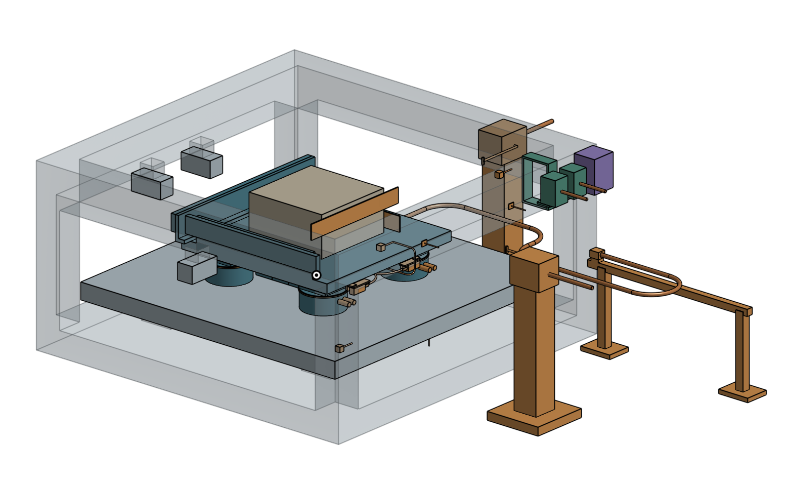
A compact XY stage concept for wafer positioning.
My role Architecture, CAD, FEA, and metrology integration.
01 / ENGINEERING PROBLEM
Research objective
This research began with UBC’s Mechatronics & Instrumentation Group’s need to explore a compact stage for wafer positioning. I investigated a design with 100 mm of travel on each axis, a 2 kg payload, and a 1 µm positioning target per axis. The main challenge was limiting structural and measurement errors at a point 25 mm above the mounting face.
02 / METHODS & ANALYSIS
Design and analysis
CAD and simulation results
Click any figure to enlarge
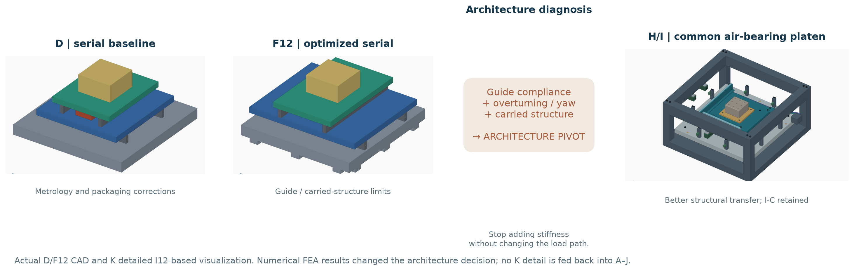
From stacked axes to a planar stage
Stacked stage
Passive yaw restraint; heavier carried assembly and accumulated compliance.
Planar stage
Lower mass and shorter load path; active yaw, pneumatics, and a larger reference frame.
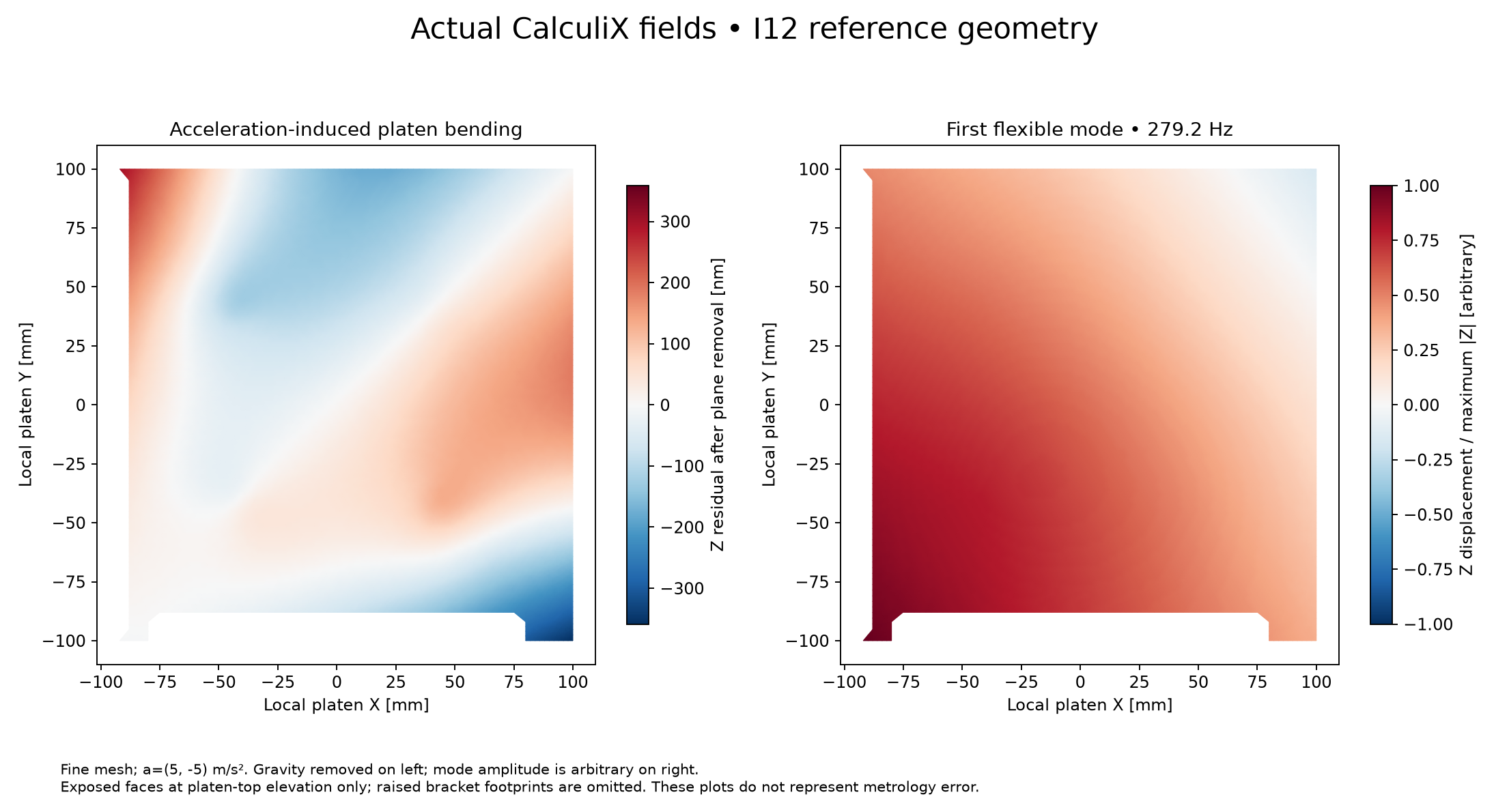
Structural analysis
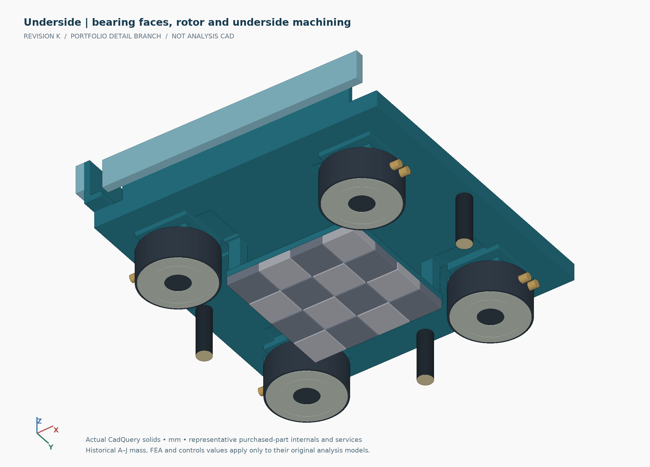
I also added sensors and mounts in CAD to assess their effect on mass, clearance, and future performance testing.
03 / RESULTS & OUTCOME
Preliminary results
Testing next
- BearingsStiffness and load sharing.
- StructureCompliance and modes.
- PositioningAccuracy, repeatability, and drift.
Disturbance-free cases used model-aware feedforward and 20% force headroom. Disturbed cases took 160–440 ms, exceeding 100 ms; disturbance rejection needs further research. Package target remains unmet.
Preliminary sensor impact
- Added mass
- +87 g
- Conservative margin to 5 kg
- 110 → 23 g
- Clearance
- ±63 mm reserve
CAD estimates; dynamic effects untested.