Simba GaoMECHANICAL / MECHATRONICS
← All projects

INDEPENDENT ENGINEERING INQUIRY

Precision Hexapod Design & Optimization

I developed a compact six-axis stage and a reusable geometry optimizer, reducing the stage’s median simulated positioning error from 139.5 to 0.99 µm RMS through calibration and compensation.

My role Mechanical design, kinematic and structural modeling, virtual calibration, and optimizer development.
  • Mechanical CAD
  • Kinematics
  • Structural FEA
  • Calibration
  • Design optimization
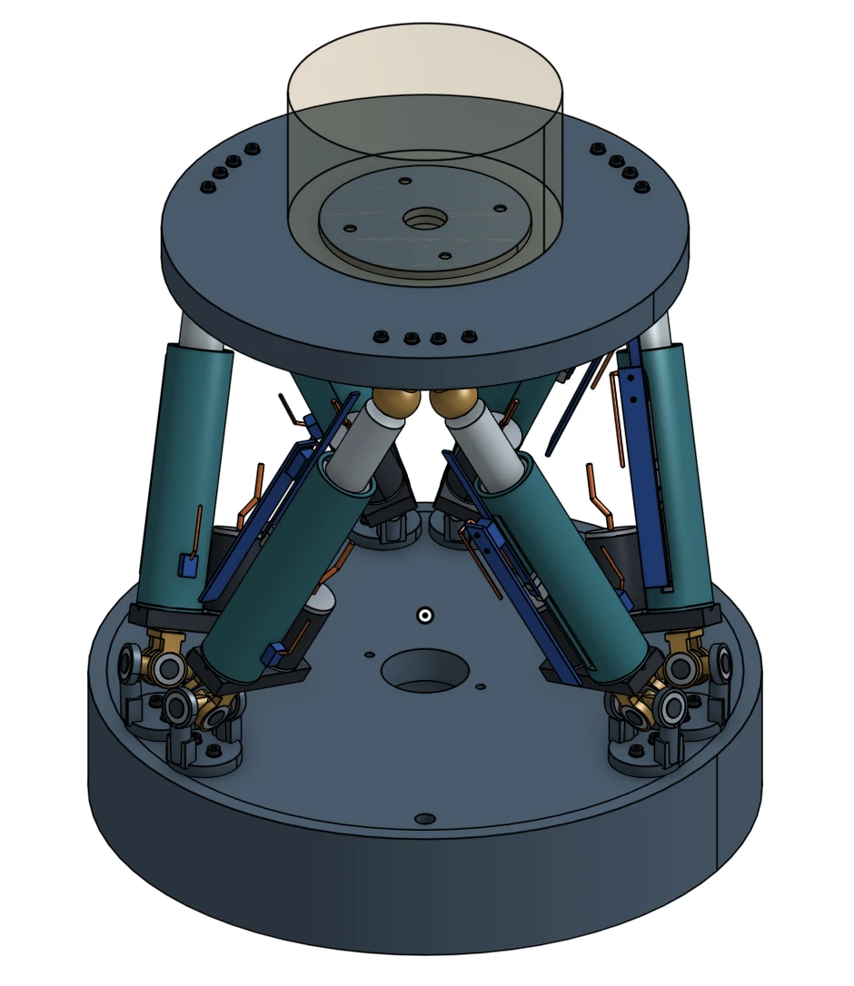
Compact six-axis hexapod CAD with six actuators, upper payload platform, joint assemblies, and base.
Selected compact design · CAD concept, not tested hardware
Explore the 3D model

Rotate the assembly, inspect individual actuators, and try the cutaway view.

Open full screen ↗
7 kgModeled payload · selected compact design
±10 mm / ±5°Translation / rotation workspace
368.2 mmSwept diameter

01 / ENGINEERING PROBLEM

Six-axis motion in a compact stage

The goal was a compact platform that could position and orient a payload with <5 µm translation error while keeping its lowest structural mode above 100 Hz. Leg geometry, joint compliance, and temperature all affect that result. I investigated one detailed design and developed a configurable optimizer to explore the tradeoffs for other requirements.

02 / METHODS & ANALYSIS

From geometry to predicted performance

Click figures to enlarge

01

Develop the actuator and supporting structure
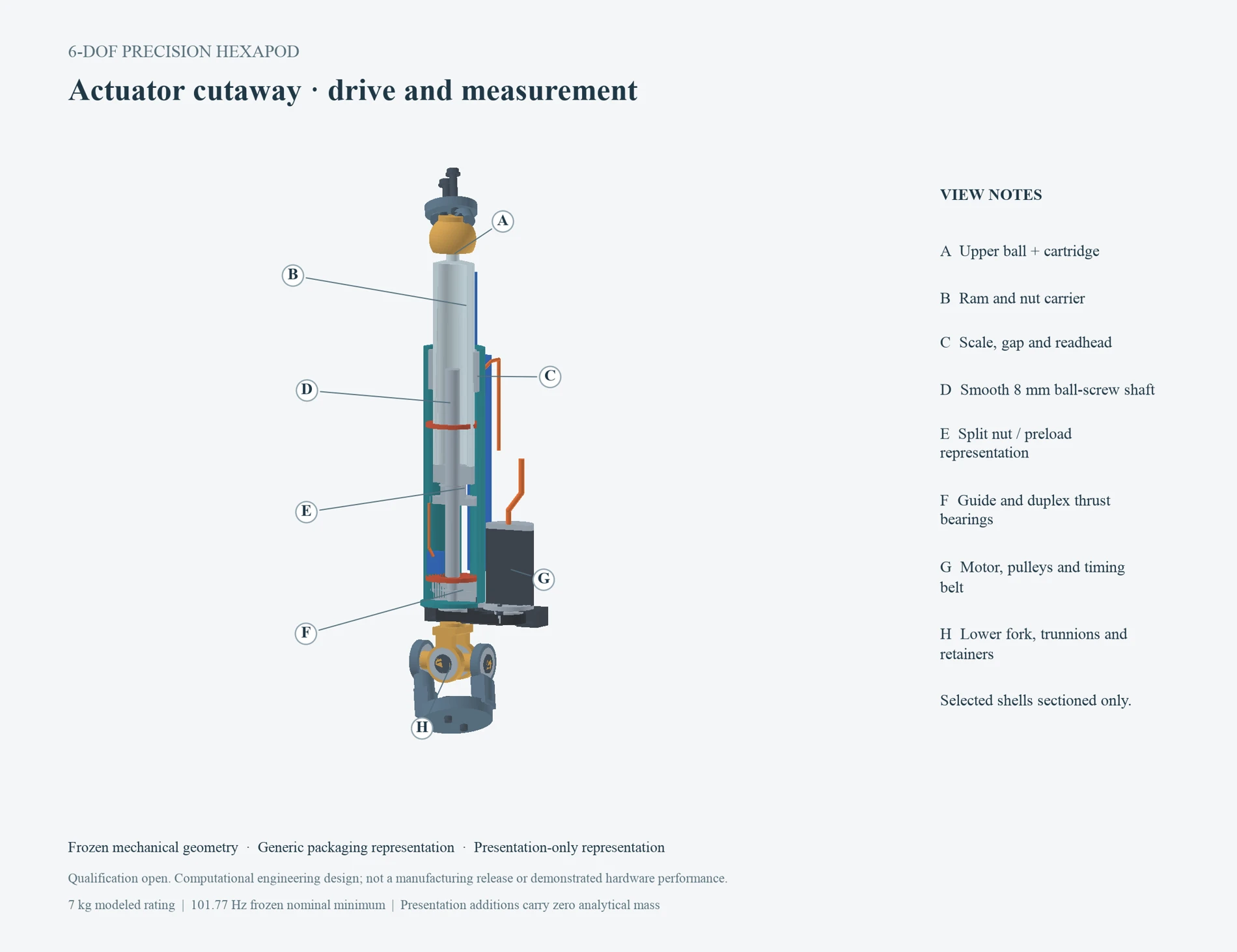
Actuator cutaway identifying the upper joint, ram, encoder, ballscrew, bearings, belt drive, and lower universal joint.

Ballscrew actuator · drive, joints, and sensing

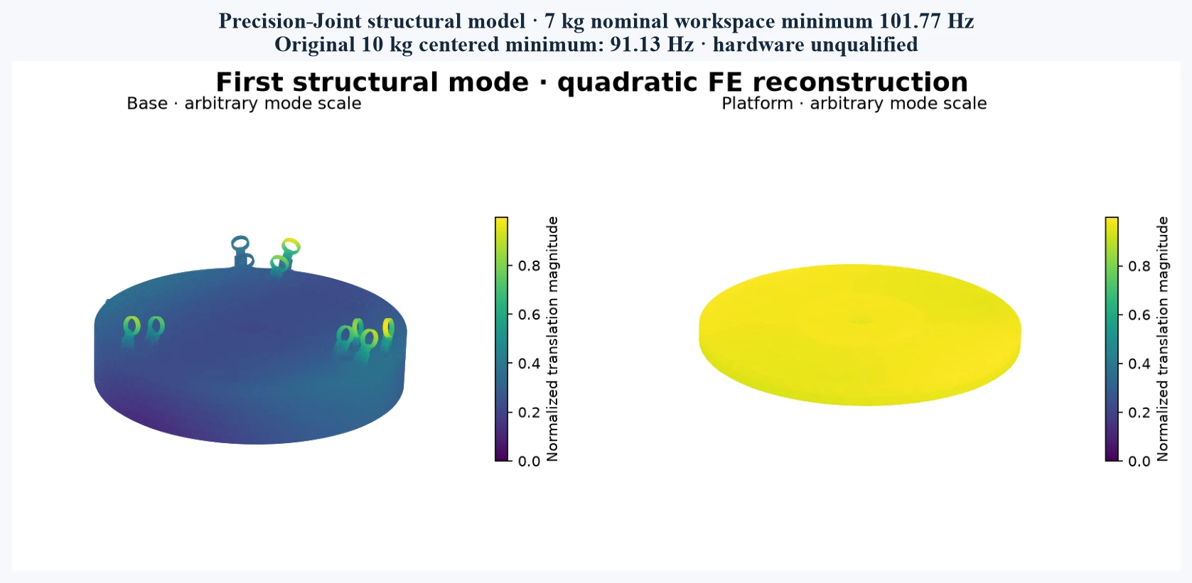
Finite-element reconstruction of the first structural mode: modeled minimum 101.77 Hz at 7 kg; 91.13 Hz at the original 10 kg payload.

Structural mode · normalized deformation, not displacement

I retained the selected joint geometry while refining the base, towers, and bearing supports. Structural analysis supported a 7 kg rating at 101.77 Hz; the original 10 kg case remained below 100 Hz. Clearance checks also ruled out two alternative layouts.
02

Calibrate geometry, then compensate predictable errors
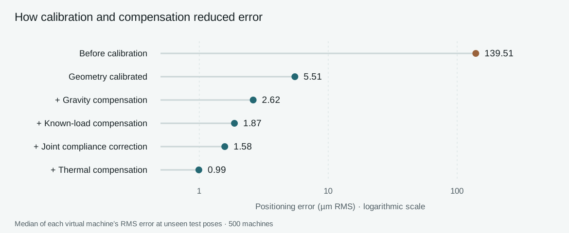
Median positioning error · µm RMS

  1. Before calibration139.51
  2. Geometry calibrated5.51
  3. + Gravity compensation2.62
  4. + Known-load compensation1.87
  5. + Joint compliance correction1.58
  6. + Thermal compensation0.99
500 virtual machines · unseen test poses
I fitted geometry from synthetic measurements, then compensated gravity, known loads, joint compliance, and temperature. Independent test poses checked whether those corrections generalized beyond the calibration data. Each virtual machine had its own manufacturing and measurement errors.
03

Make the design search reusable

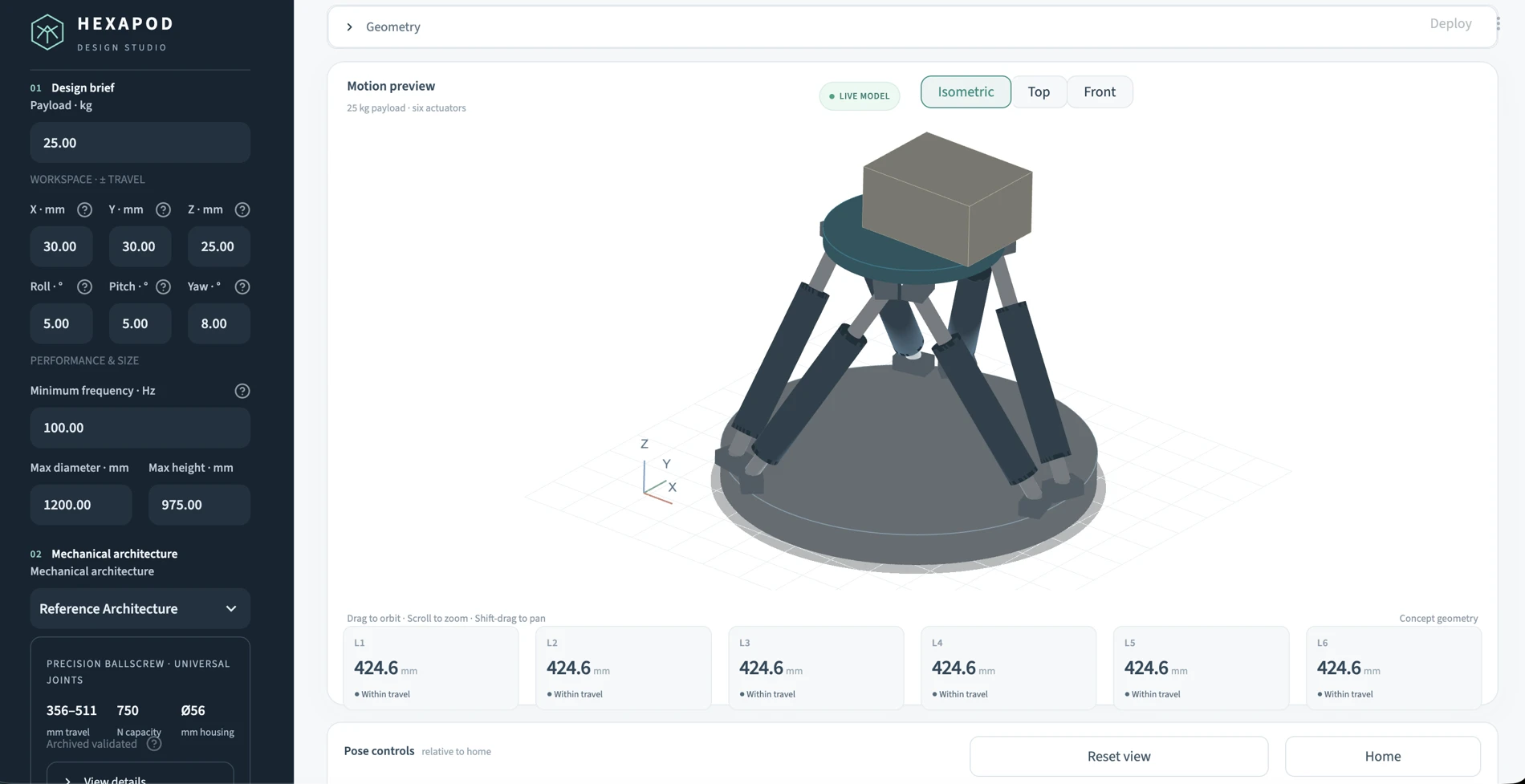
Hexapod Design Studio with configurable payload, travel, rotation, frequency, and size requirements alongside an interactive six-leg motion preview.
32,715Geometries evaluated
6Finalists checked in detailed models
2.88%Largest frequency prediction difference
I separated requirements from actuator and joint definitions, then screened motion, forces, clearance, and stiffness before detailed checks. In a separate 25 kg reference study, the best full-workspace finalist reached 59.93 Hz: geometry changes alone did not achieve the >100 Hz target.

03 / RESULTS & OUTCOME

A quantified design and its limits

SIMULATED RESULTS
PHYSICAL VALIDATION PENDING
500 / 500Virtual machines within
<5 µm / <50 µrad error targets
3.31 µmLargest evaluated positioning error
14.53 µrad largest angular error
101.77 HzLowest evaluated structural mode
7 kg · nominal supports

The compact design met the precision targets across independently calibrated virtual machines under the assumed uncertainty model; this is not measured accuracy or manufacturing yield. The optimizer separately identified the 25 kg reference architecture’s frequency limit. Next: measure joint reversal, actuator repeatability, and mounting stiffness, then validate calibration under changing loads and temperatures.