Simba GaoMECHANICAL / MECHATRONICS
← All projects

AEROTECH / MECHATRONICS R&D · 2026

Eddy-current Modeling and Analysis

I built a modeling workflow for precision actuators and achieved 70% recovery in position-tracking magnitude and phase through simulated design changes.

My role · Mechatronic Engineering InternAnalytical modeling, automated electromagnetic FEA, mitigation studies, and actuator-design tools.
  • Python
  • FEMM
  • ANSYS Maxwell
  • Actuator dynamics
  • Design of experiments
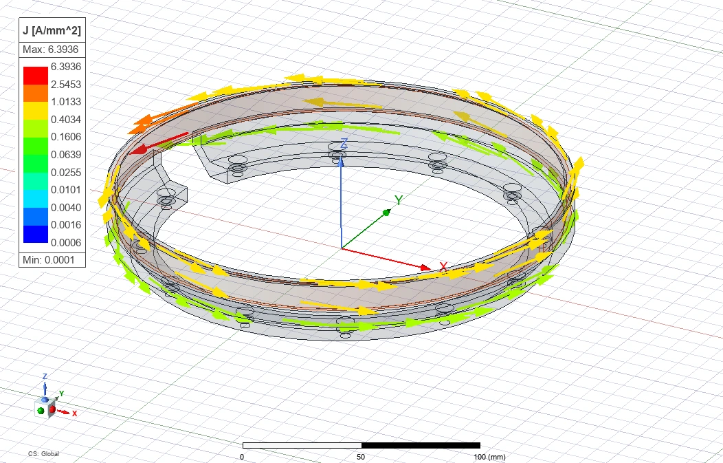
Electromagnetic simulation showing induced currents circulating around an aluminum voice-coil support.
Simulated current paths in the aluminum coil support
70%Position-tracking recovery
Magnitude and phase · simulation
768Geometry and magnet configurations
Automated FEMM study
3Reusable engineering tools
Model selection, prediction, and controls

01 / ENGINEERING PROBLEM

Current tracking was only part of the picture

Conductive structures near a voice coil can generate unwanted currents that weaken and delay its force, even when the commanded coil current is accurate. Aerotech needed a way to predict those effects before building hardware. My objective was to connect actuator geometry to force and position response, then evaluate practical design changes.

02 / METHODS & ANALYSIS

From current paths to design changes

Figures from the project report
Click to enlarge

01

Model the actuator and check the results
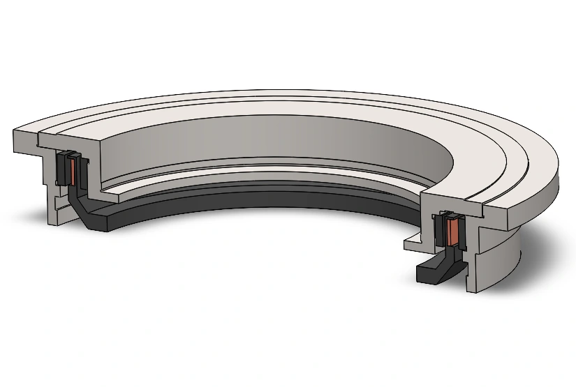
Cutaway CAD of the ring-shaped voice-coil actuator used in the electromagnetic study.

Actuator cross-section

QUICK ESTIMATEEquivalent electrical circuitRepresent the main eddy-current path as a coupled, closed conducting loop.
GEOMETRY & FREQUENCY SWEEPS2D FEMM analysisCheck the simplified model across many cylindrical designs.
MOTION & FINITE CURRENT PATHS3D / transient Maxwell analysisResolve slot ends and motion that the simpler model cannot capture.
I connected the electromagnetic models to current, force, and position response. Published benchmarks checked the simulation setup; errors ranged from 0.08–2.4% across four reference cases.
02

Turn geometry sweeps into design tools
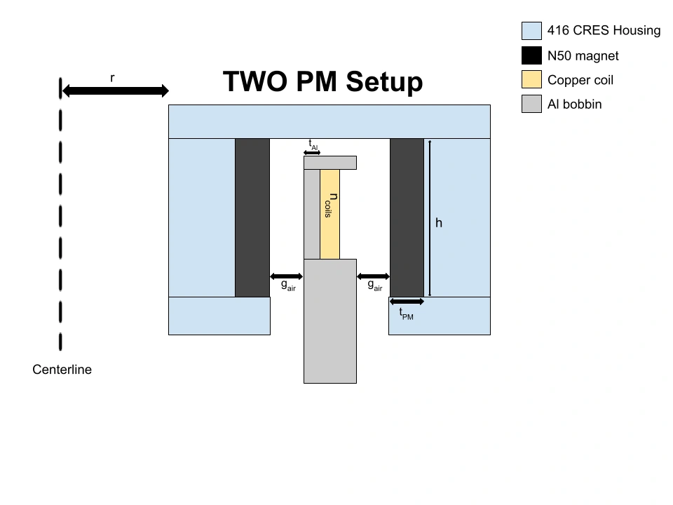
Parameterized cylindrical actuator cross-section showing radius, height, aluminum wall thickness, and air gap.

768 configurations · radius, height, wall thickness, gap, and magnet arrangement

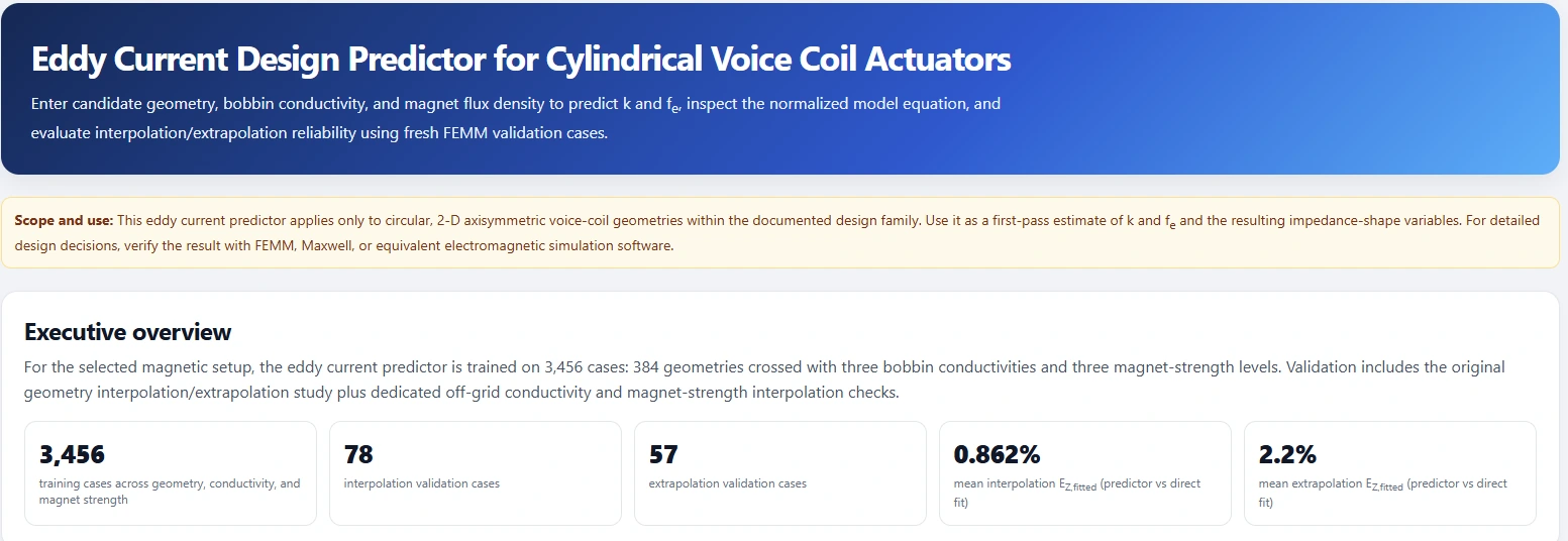
Eddy-current design predictor interface developed to estimate candidate actuator behavior without a new full simulation sweep.
Height + wall thicknessStrongest geometry effects on response shape
Radius + coil turnsPrimarily scale electrical quantities
I automated the geometry study to determine when a simplified model was useful, then built tools for model selection, response prediction, and closed-loop analysis. This let engineers screen a candidate design before committing to a detailed simulation.
03

Interrupt the unwanted current paths
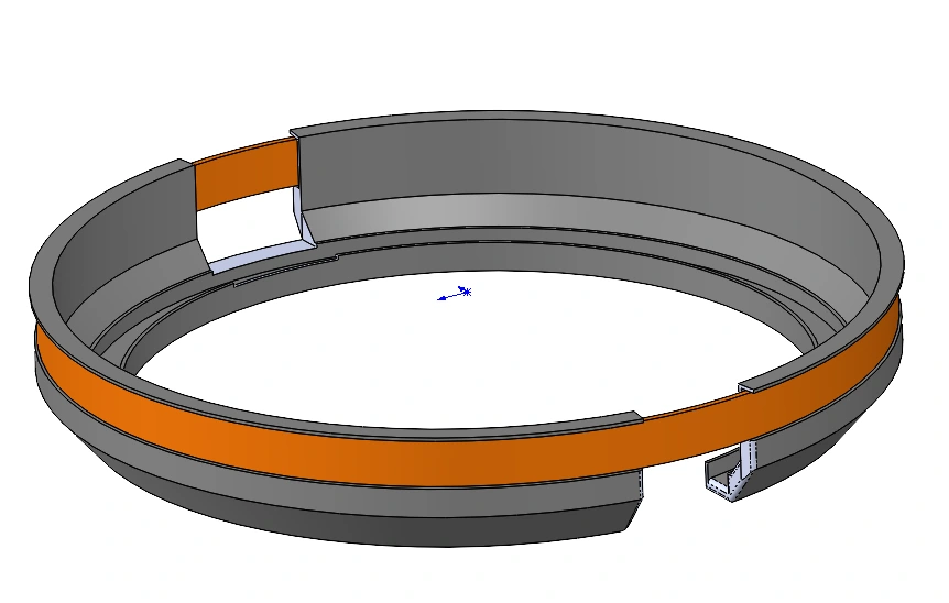
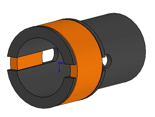
Ring-shaped actuator CAD with interruptions in the conductive bobbin to weaken circulating eddy currents.

Ring actuator · segmented bobbin

DFM actuator CAD showing the slotted bobbin evaluated for position-tracking recovery.

Linear actuator (DFM) · slotted bobbin

I evaluated slots and segmentation to reduce the aluminum structure’s opposing force while retaining the intended coil force. The electromagnetic improvement came with structural and thermal tradeoffs: stiffness, stress concentrations, and heat conduction still needed assessment.
Learn more: model checks and tool outputs

What the benchmark checks establish

These checks test the simulation methods against published examples and an analytical solution. They do not establish accuracy on Aerotech hardware.

0.08%Static electrical and magnetic quantities
FEMM woofer example
0.41%AC electrical and force quantities
FEMM SSF-082 example
0.78%Levitation force and displacement
TEAM 28 benchmark
2.4%Motion-induced drag
Moving-plate analytical solution
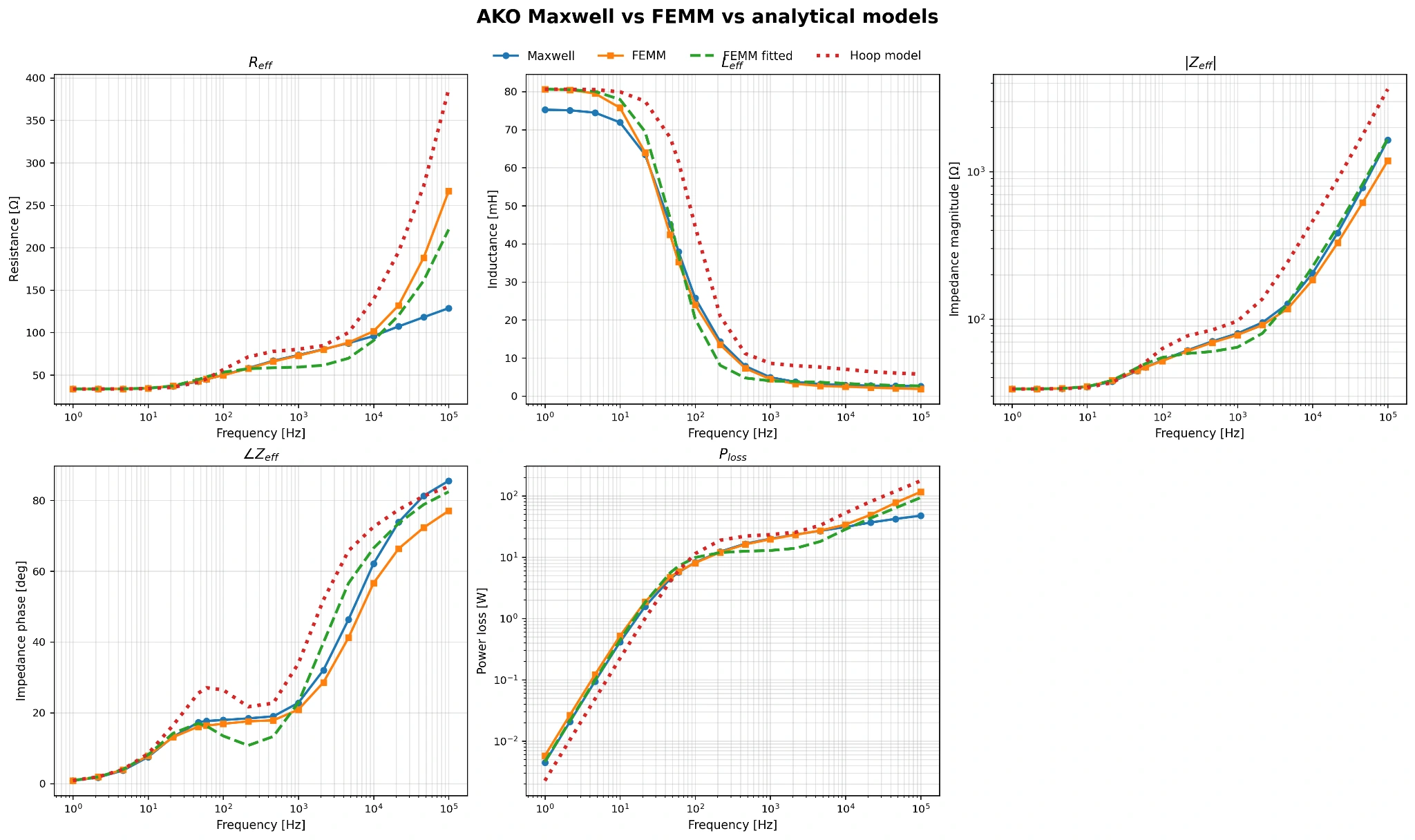
AKO actuator comparison of FEMM, Maxwell, and two analytical models for resistance, inductance, impedance, phase, and loss.
The fitted circuit model generally matched the simulations better than the geometry-only hoop model. Agreement depended on geometry and frequency; high-frequency mesh resolution limited some Maxwell comparisons.
Analytical model validity explorer interface for reviewing the parametric simulation database.
Model validity explorer: choose where a simplified model is adequate.
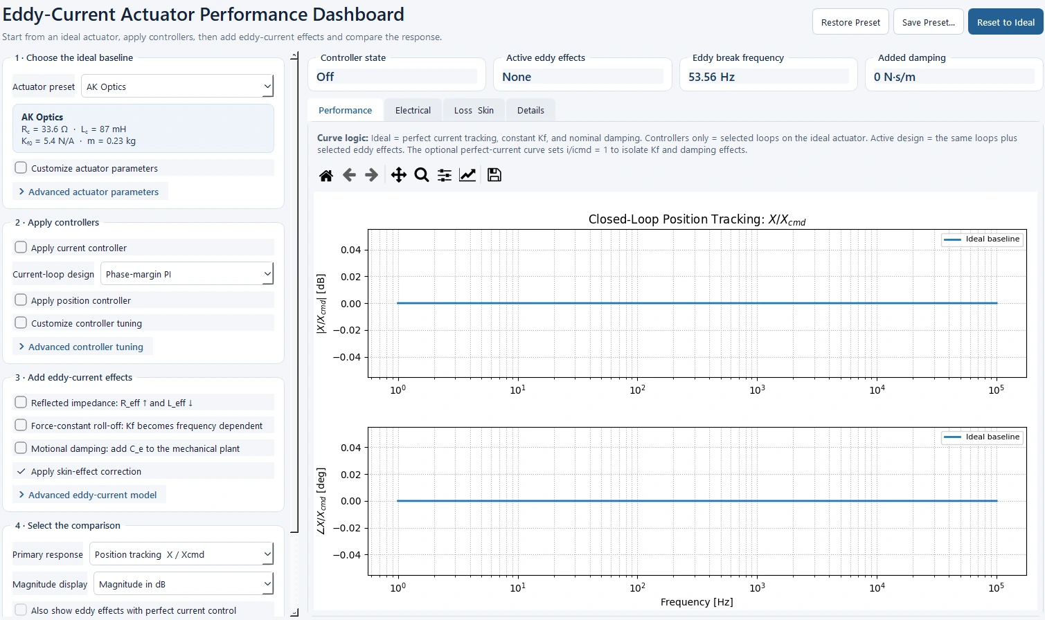
System performance simulator interface with actuator properties and closed-loop response plots.
System simulator: trace electrical and force changes through to position tracking.
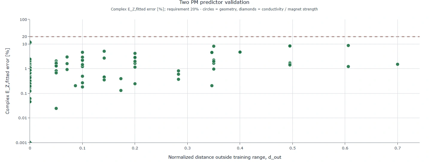
Design predictor validation plot showing parameter prediction errors across 145 test cases.
Reported parameter-prediction errors stayed within 20% across 145 interpolation and extrapolation cases. This checks the predictor against the simulation database, not hardware.

03 / RESULTS & OUTCOME

Position tracking after mitigation

SIMULATION RESULTS
HARDWARE VALIDATION PENDING

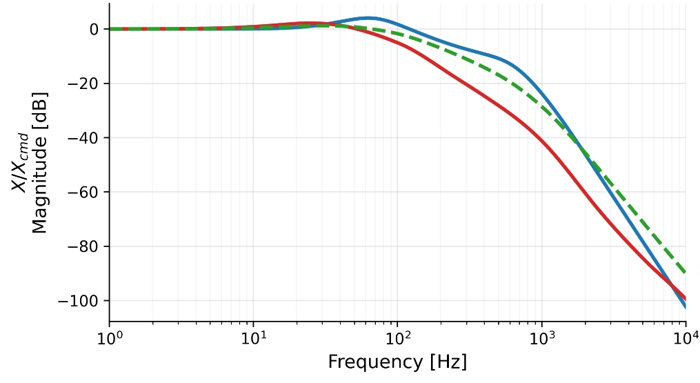
Magnitude · motion amplitude

DFM position-tracking Bode magnitude plot comparing ideal, unmitigated, and mitigated simulated responses across frequency.

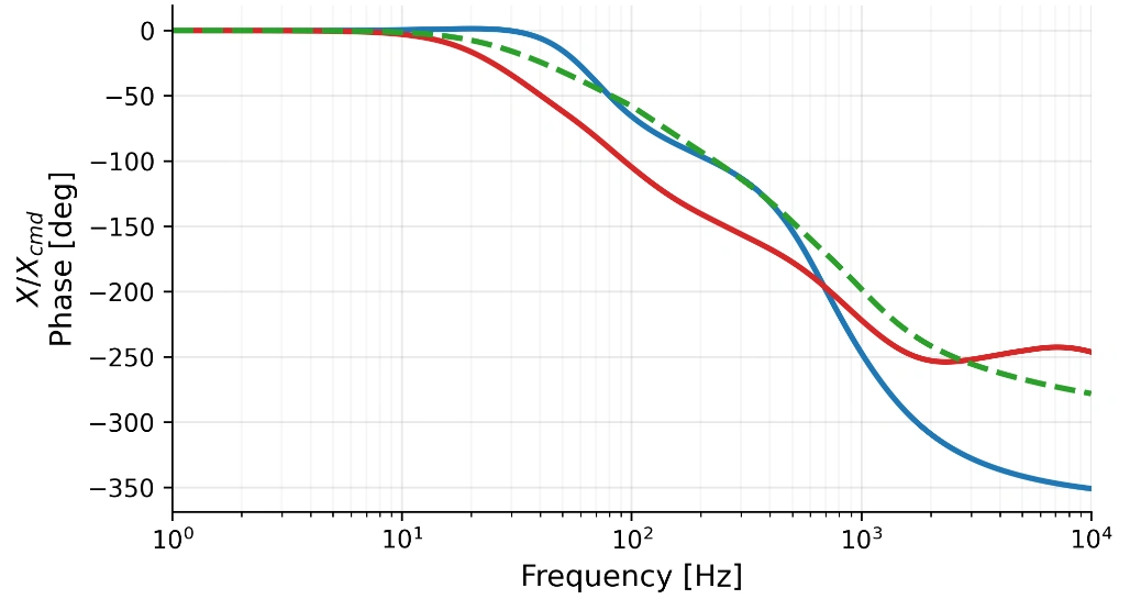
Phase · motion timing

DFM position-tracking Bode phase plot comparing ideal, unmitigated, and mitigated simulated responses across frequency.
  • Ideal
  • Before mitigation
  • After mitigation
DFM position response, X/Xcmd: actual position relative to commanded position. The curves show how slotting changes motion amplitude and timing across frequency.
70%Recovery in position-tracking
magnitude and phase

Interrupting the conductive current paths reduced eddy-current effects and brought the simulated position response closer to ideal in the affected operating range. Hardware frequency-response measurements and structural/thermal checks remain before adopting the design.