Simba GaoMECHANICAL / MECHATRONICS
← All projects

CMU / MECHATRONIC SYSTEMS PROJECT

Compact Low-Cost Dynamic Drone Propeller Balancer

A prototype that combines vibration and rotor-position measurements to calculate corrective mass placement.

My role Led mechanical design and sensor integration; implemented rotor tracking, ODrive control, and the analysis GUI within a five-person team.
  • Rotor dynamics
  • Vibration sensing
  • Motor control
  • Signal processing
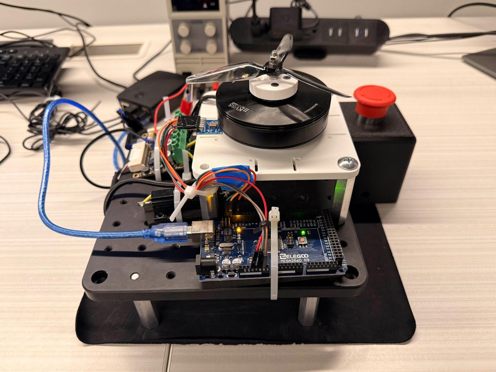
Built propeller-balancing rig with motor, propeller, accelerometer, controller, encoder interface, and emergency stop.
Built prototype · experimental tests at 600 rpm
600 rpmDocumented test speed
Synchronous magnitude & phase
$948Prototype BOM · $1,000 budget

01 / ENGINEERING PROBLEM

Locating the imbalance

The goal was a compact instrument that could identify propeller imbalance and determine how much mass to add or remove, and where. The challenge was preserving rotor phase while separating rotational vibration from noise and fixture dynamics. I worked on integrating the mechanical rig, sensing, and control into a repeatable measurement workflow.

02 / METHODS & ANALYSIS

Design and measurement

Hardware, analysis, and test data
Click any figure to enlarge

01

Mechanical and sensor integration

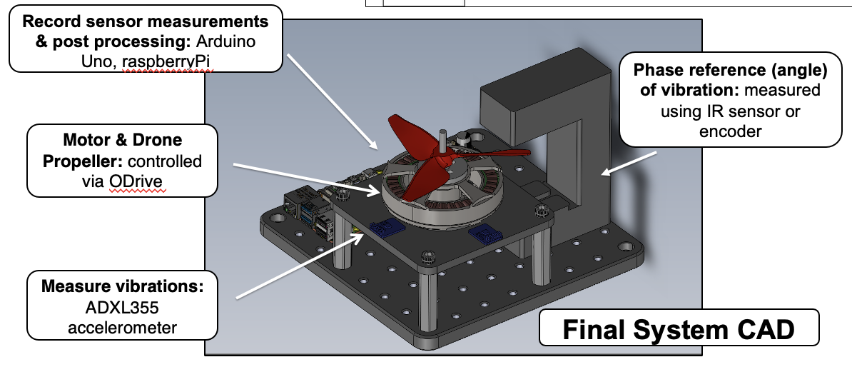
Annotated system CAD showing motor and propeller, accelerometer locations, phase reference, and data acquisition.
The IR break-beam sensor could not reliably capture blade passage, so the final system used encoder-based rotor tracking. The ADXL355 measured vibration at the motor plate.
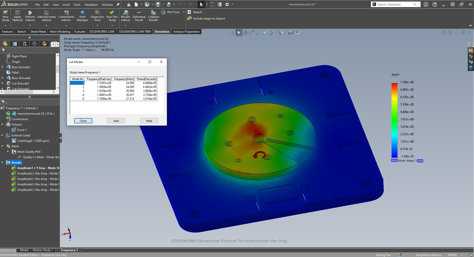
SolidWorks motor-plate modal analysis showing a predicted first mode of 24,505 Hz under the model constraints.
Motor-plate FEA screened for resonance near the 30 Hz blade-pass frequency at 600 rpm. This plate-only model did not validate the dynamics of the assembled rig.
02

Synchronous vibration analysis

ODrive + motorEncoder position θ(t)
Rotor vibration · ADXL355Acceleration a(t)
TIME ALIGN · STEADY-STATE GATESynchronous projection
1× ROTATIONAL COMPONENTMagnitude + phase
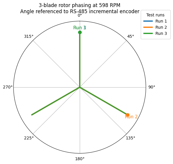
Three-blade rotor phase referenced to the encoder in three recorded runs at 598 rpm.

Encoder-referenced rotor phase

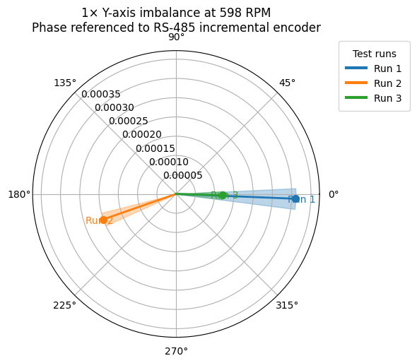
Measured 1× Y-axis vibration vectors for three runs at 598 rpm, referenced to the encoder.

Measured 1× vibration vectors

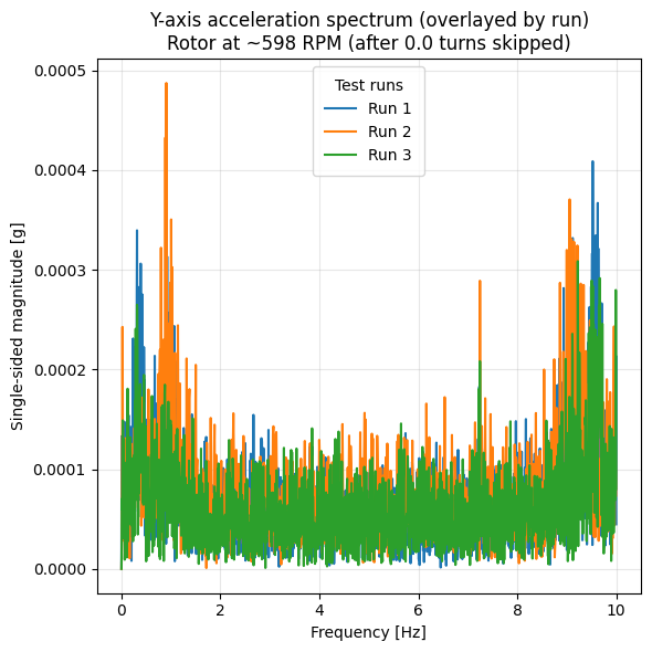
Measured Y-axis acceleration spectra from three runs near 598 rpm, overlaid from zero to ten Hz.

Measured acceleration spectra

Time-aligned, steady-speed records yielded the 1× vibration vector through synchronous projection, with FFTs checking spectral content. The three recorded runs show phase and amplitude variation, not a before/after balancing result.
03

Calculating the correction

  1. 01 / BASELINEMeasure V₀Initial vibration vector
  2. 02 / TRIAL MASSAdd mₜ at θₜKnown radius rₜ
  3. 03 / RESPONSEMeasure VₜChange: Vₜ − V₀
  4. 04 / CORRECTIONCalculate m꜀, θ꜀Apply and remeasure
INFLUENCE COEFFICIENTα = (Vₜ − V₀) / Uₜ
CORRECTION UNBALANCEU꜀ = −V₀ / α

Uₜ = mₜrₜ∠θₜ  ·  m꜀ = |U꜀| / r꜀  ·  θ꜀ = arg(U꜀)

The known trial mass relates vibration change to mass and angle at a fixed speed. The influence coefficient then converts the initial vibration vector into a correction mass and angular location.

03 / RESULTS & OUTCOME

Prototype test results
PHYSICAL PROTOTYPE · KNOWN-MASS TESTS
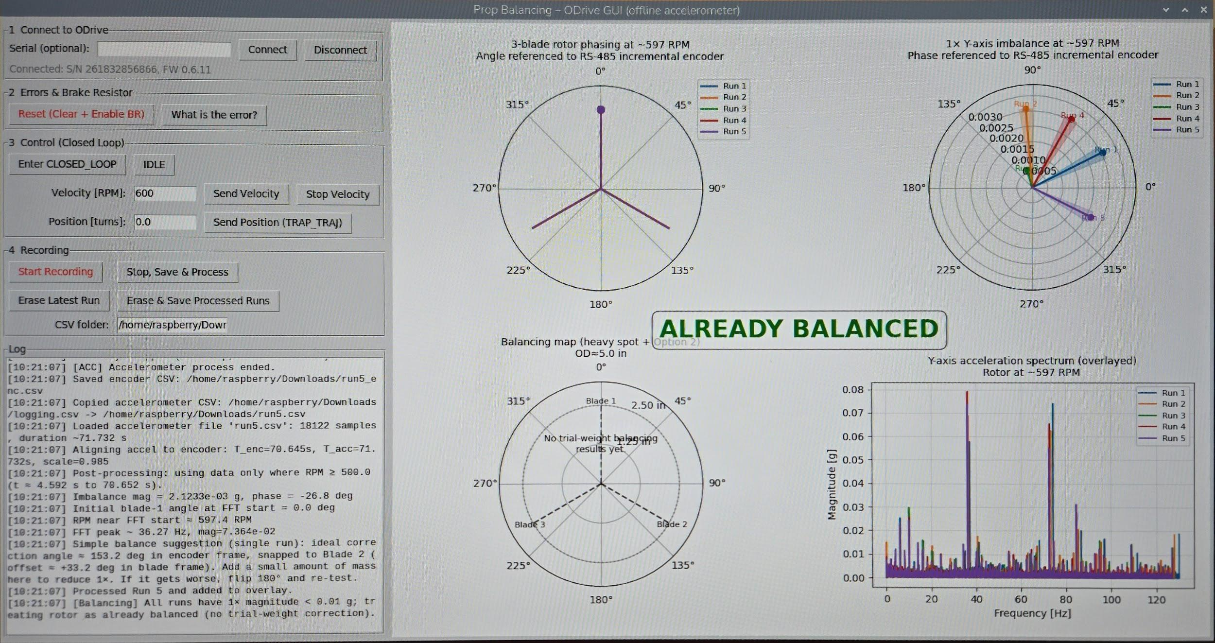
Original analysis GUI showing rotor phase, synchronous vibration vectors, FFT, and motor controls.
Implemented GUI · motor-only reference run
±4 gReported correction-mass error
for a 12 g trial mass
6 / 12 / 22 gKnown masses tested on a propeller blade
1 min / runAcquisition across five test conditions

Known-mass tests demonstrated imbalance detection and corrective-weight recommendations. High-speed performance remained unverified because clean phase capture was limited by the motor/encoder pairing. A quantified post-correction vibration reduction and repeatability limit were not established.