UNIVERSITY OF MICHIGAN / PRECISION SYSTEMS DESIGN LAB
Diaphragm Flexure Fabrication and Testing
I helped manufacture and test a research flexure, with experimental results agreeing with the model within 9%.
My roleCAD refinement, manufacturing and assembly planning, alignment, and stiffness testing within a four-person team. The sponsor supplied the original architecture and FEA.
01 / ENGINEERING PROBLEM
Build a precise, testable flexure
The sponsor’s sandwich flexure was intended to resist in-plane motion while allowing compliant out-of-plane travel. Our task was to make that architecture manufacturable, align its thin features, and measure its stiffness. Manufacturing lead times and tolerance limits shaped the final assembly.
02 / METHODS & ANALYSIS
From research geometry to a test assembly
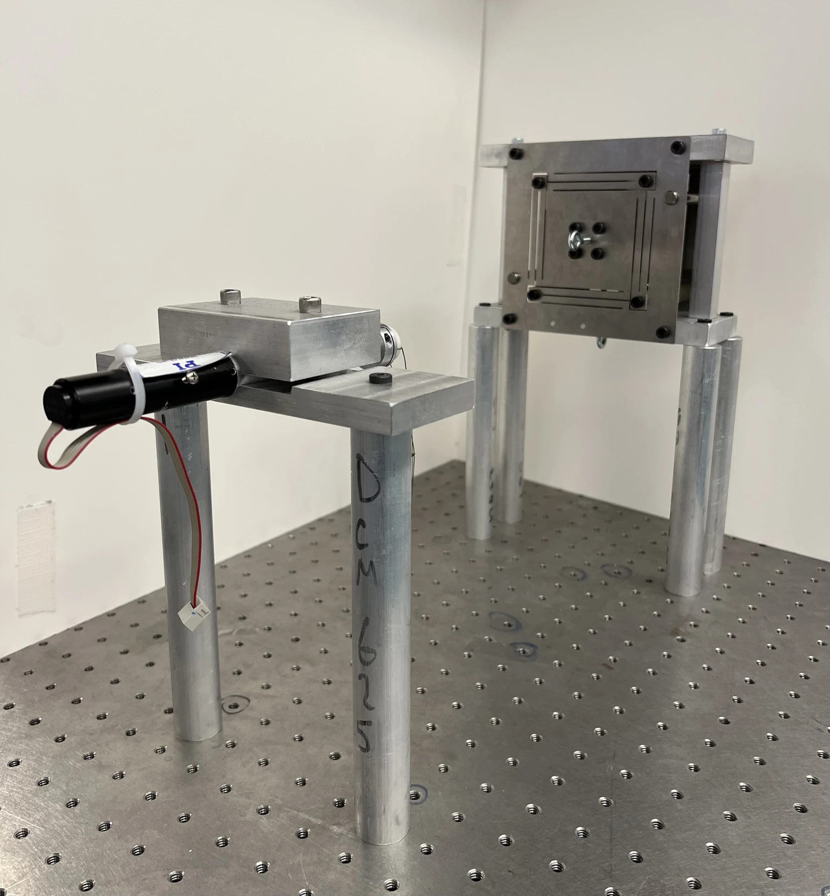
Project figures and hardware
Click images to enlarge
Choose fabrication methods around the geometry
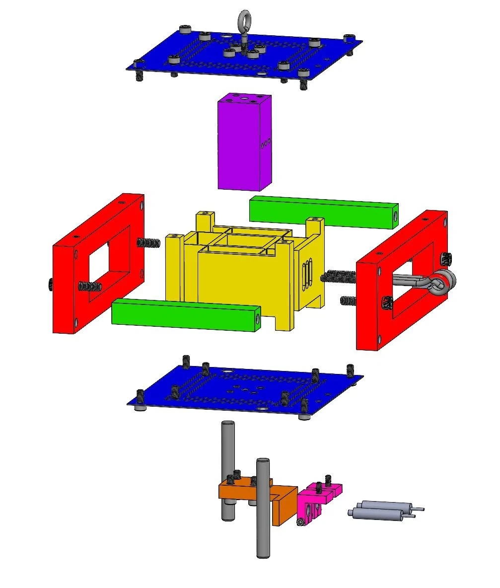
- Thin folded-beam layersWaterjet-cut aluminum 7075
- Complex center interconnectMonolithic aluminum 7075 · outsourced wire EDM
- Frames and sensor mountsMilled parts; 6061 where strength and availability allowed
I contributed to the CAD and fabrication plan, reserving wire EDM for the complex center piece and using waterjet and milling for the remaining parts. The team balanced precision, cost, and lead time rather than assigning one process to every feature.
Align the layers and instrument the load path
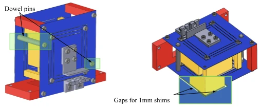
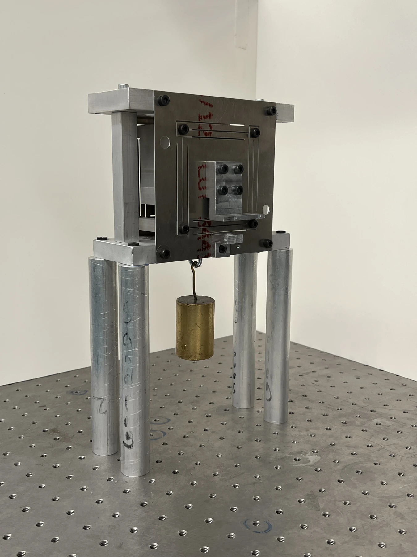
Two dowel pins constrained relative layer motion; 1 mm shims aligned the center interconnect. Probe mounts and loading hooks made the assembly testable. Waterjet beam-gap variation reached about 100 µm, exceeding the intended 40 µm variation and motivating a more precise cutting process.
03 / RESULTS & OUTCOME
In-plane response measured
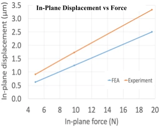
The prototype was fabricated, aligned, and tested. Its measured in-plane response followed the FEA trend, with lower stiffness than the ideal model. Assembly compliance and manufacturing variation remained plausible contributors. Out-of-plane and rotational testing remained incomplete.